
NLSC: SENIOR THREE AGRICULTURE
SENIOR THREE AGRICULTURE Agriculture Senior Three, as outlined in...
SENIOR THREE AGRICULTURE Agriculture Senior Three, as outlined in...

SENIOR THREE CHEMISTRY Chemistry is the branch of science that focuses...

SENIOR THREE GENERAL SCIENCE General Science Senior Three, as outlined...

SENIOR THREE NUTRITION AND FOOD TECHNOLOGY The Senior Three Nutrition and...

SENIOR THREE CHRISTIAN RELIGIOUS EDUCATION The Senior Three Christian...
New A-Level Syllabus Stay ahead in your academic journey with Yaaka...

WHAT IS CURRENT ELECTRICITY
Electric current in simple terms are electrons in motion along a path, regardless of the number of electrons flowing. The path may be a conductor such as copper, silver and aluminium. Free electrons can be forced to move from one region of the conductor to the other.
Current
Current is the rate at which an electric charge flows in a conductor. It is the number of electrons passing a given point in a second. This means that if more electrons pass by a given point, the current is greater.
The symbol for current is the letter “I”. Electrical current is measured in Amperes or “amps”.
Voltage
Voltage measures the difference in electrical energy between two points of a circuit. Voltage is measured in Volts and represented by the letter ‘V’
Current and voltage can be very confusing.
Here is an illustration to help you. Think of electrical charge, current and voltage as a huge water tank connected to a pipe.
Water = Charge
Pressure = Voltage
Flow = Current
The water in the tank represents electric charge. The more water in there, the more the charge. Voltage is like pressure. The more the water, the higher the pressure (voltage) at the end of the pipe.
In the diagram above, there is voltage at point A, but no current, because the tap is closed and the water is NOT flowing. This means there can be voltage without current, but no current without voltage.
At point B, the tap is opened and water flows. At this point, there is both voltage and current because there is a flow.
If we open the tap to drain some water out, the pressure will reduce (lower voltage).
Just as a pump can be used to force water through a pipe, we can use an external source of power (electromotive force) such as a battery to push free electrons in conductors to flow from place to place along a path. Current moving in one direction is called Direct Current. Electrons in the atom do not move in a straight direction. There undergo repeated collisions with other electrons in nearby atoms. During these collisions, free electrons are knocked off towards the positive end of the conductor.
Resistance
Resistance can be understood in two ways.
In terms of electron flow, it is the difficulty that electrons face as they flow inside a conductor (wire). A thin wire means that the electrons have little space to flow, and they bump into each other, therefore the flow is not smooth enough. Here, we say there is more resistance. In a thicker wire, there is more space for the electrons to move. There is less bumping into each other and therefore there is less resistance.
In terms of resistors on an electrical circuit, it is anything that gets in the way of the electricity. Examples include bulbs, lamps, buzzers and so on. These resistors use up some of the electricity. Without them, there could be a short circuit.
Ohm’s law
This law relates the current flowing through a conductor and the voltage drop across that section of the conductor. The law states: the current flowing through a conductor is directly proportional to the potential difference across its ends provided temperature and other physical factors are kept constant. The following set up can be used to investigate Ohm’s law:
A graph of voltage against current is a straight line through the origin. Hence voltage drop across the conductor is directly proportional to the current through it;
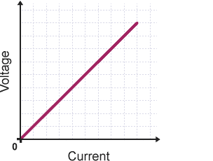
Vα I
V/I = constant
The constant is known as resistance R of the conductor T under investigation.
Thus, V/I= R
Or V= IR.
Hence the slope of a voltage—current graph is equal to the resistance R of the conductor T. electrical resistance can be defined as the opposition offered by a conductor to the flow of electric current. It is measured using an ohmmeter.
The SI Unit of electrical resistance is the ohm (Ω). Other units include kilo-ohm (kΩ) and mega-ohm (MΩ);
1Ω= 10-3kΩ
1Ω= 10-6MΩ
Materials which obey Ohm’s law are said to be ohmic materials while those which do not obey the law are said to be non-ohmic materials. The graph of voltage against current for non-ohmic materials is a curve or may be a straight line but does not pass through the origin.
The inverse on resistance is called conductance;
Conductance= 1/ resistance R.
Example
Calculate the current flowing through a 8Ω device when it is connected to a 12V supply.
solution
I= V/R
I= 12V/8Ω =1.5A
Factors affecting the resistance of a conductor
There are three main factors that affect the resistance of a conductor:
Temperature
Increase in temperature enhances the vibration of the atoms and thus higher resistance to the flow of current.
Length of the conductor L
The resistance of a uniform conductor increases with increase in length.

Cross section area A
A conductor having a wider cross section area has more free electrons per unit length compared to a thin one. Hence a thicker material has a better conductivity than a thinner one. Generally, resistance varies inversely as the cross section area of the material.

Therefore, at a constant temperature resistance varies directly as the length and inversely as the cross section area of the conductor;
RαL/A
R= (A constant * L/A)
Or simply, AR/L= constant
The constant is called the resistivity of the material;
Resistivity ϱ= (cross section area A * resistance R) / length L.
Resistivity is measured in ohm-metre (Ωm).
Example
1. A wire of resistance 3.5Ω has a length of 0.5m and cross section area 8.2 * 10-8m2. Determine its resistivity.
solution
Resistivity ϱ= AR/L = (8.2*10-8m2*3.5Ω)/0.5m
= 5.74*10-7Ωm
2. Two conductors A and B are such that the cross section area of A is twice that of B and the length of B is twice that of A. If the two are made from the same material, determine the ratio of the resistance of A to that of B.
solution
R=ϱL/A
Therefore, RA= ϱALA/AA
And RB= ϱBLB/AB
Where LB=2LA
AB= 1/2AA
And ϱA= ϱB
Hence RA=ϱALA/AA and
RB= 2ϱALA/0.5AA = 4ϱALA/AA
Thus RA/RB=ϱALA/AA = 1/4
4ϱALA/AA
RA: RB= 1:4
Resistors
A resistor is a specially designed conductor that offers a particular resistance to the flow of electric current. There are three main groups of resistors:
Measurement of resistance
Three methods may be used:
Voltmeter- ammeter method
In this method, the current flowing through the material and voltage across its ends are measured and a graph of voltage against current plotted. The slope of the graph gives the resistance offered by the material.
The wheatstone bridge method
A wheatstone bridge consists of four resistors and a galvanometer connected as shown below:

The values of three out of the four resistors must be known. The value of one of the resistors is adjusted to a point that the galvanometer does not deflect. At this point, the voltage drop across R1 is equal to that across R2. Similarly, the voltage drop across R3 is equal to that across Rx. Note that the current I1 flowing through R1 is equal that through R3. Also, the current I2 through R2 is the same to that through Rx.
Therefore, I1 R1= I2R2…………………………. i
I1 R3= I2Rx…………………………. ii
Dividing equation (i) by (ii), we get;
R1/R2= R3/R4
This method is more accurate compared to the voltmeter- ammeter method since the voltmeter has some resistance against the flow of current and thus takes up some voltage.
The metre bridge method
This method relies on the fact that resistance is directly proportional to the length of the conductor.
The value of R must be known. Suppose at point K the galvanometer does not deflect, then the voltage drop across R1 equal the voltage drop across the section L1. Similarly, the voltage drop across S equals the voltage drop across the section L1. If the current through R and S is I1 and that through the section L1 and L2 is I2, then;
I1R1= I2L2 ………………………….. i
I1S=I2L1 …………………………… ii
Dividing equation (i) by (ii), we get;
R1/S= L2/L1
Resistor networks
a) Series network
When resistors are arranged in series the same current pass through each one of them. Consider three resistors connected as shown below:
From Ohm’s law, V= IR.
The voltage drop across R1; V1= IR1
The voltage drop across R2; V2 =IR2
The voltage drop across R3; V3=IR3
And the total circuit voltage V= V1+V2+V3.
Thus V= IR1+IR2+IR3=I(R1+R2+R3)
V/I =(R1+R2+R3)
But V/I = R
Thus the combined circuit resistance R=R1+R2+R3.
Generally, the effective resistance of resistors arranged in series is equal to the sum of the individual resistances.
When resistors are connected in parallel, the same voltage is dropped across them. Consider three resistors connected as shown below:
Suppose the current flowing through R1 is I1, through R2 is I2 and through R3 is I3 then:
The voltage drop across R1; V1=I1R1
The voltage drop across R2; V2=I2R2
The voltage drop across R3; V3=I3R3
But V1= V2= V3= V and I=I1+I2+I3
Therefore, I=V/R1 + V/R2 + V/R3
I/V = (1/R1 + 1/R2 + 1/R3)
But I/V= 1/R.
Hence 1/R= 1/R1 + 1/R2 + 1/R3
R is the combined circuit resistance.
Special case of two resistors in parallel
1/R= (R1+R2)/R1R2
Hence the effective resistance R= R1R2/ (R1+R2).
Generally for n resistors arranged in parallel, the effective resistance of the arrangement is given by; 1/R=1/R1+1/R2+…………..+1/Rn
NOTE: when a circuit comprise of both series and parallel connections, the arrangement is systematically reduced to a single resistor.
Internal resistance r
When a cell supplies current in a circuit, the potential difference between its terminals is observed to be lower than its electromotive force (emf). This difference is due to the internal resistance of the cell. Some work must be done to overcome this resistance and so the drop in the emf of the cell is responsible for this. The difference is referred to as the lost volt and is given by Ir.
i.e. lost volts= emf-terminal voltage
Or simply emf= terminal voltage + lost volts
The mathematical equation connecting emf, circuit current, external resistance and internal resistance of the cell is given by:
E= IR + Ir= I(R+r).
Internal resistance of a cell can be obtained experimentally.
When a graph of Voltage V against current I is plotted, the graph will appear as shown below:
The slope of the graph= -r (-internal resistance) while the y-intercept= emf of the cell.
Assignment
ASSIGNMENT : CURRENT ELECTRICITY ASSIGNMENT AND ANSWERS MARKS : 100 DURATION : 1 week, 3 days